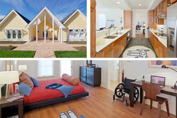
Adapt your home for a disability
Extension for Disabled
If you have a disability, we can adapt your home to make it more suitable and manageable for you.
Recommendations
Specifications
Front Access
Internal door width
Bedroom
Shower Specifications
Toilet Specifications
Wash Hand Basin Specifications
Bedroom Specifications
Specifications for Back Access
Ramps Specifications
Accessible Kitchen
Work Surfaces:
Kitchen Units:
Sink
Hob/Oven
Wall Units
Switches
Grants are available to carry out this work.
Extension for Disabled
If you have a disability, we can adapt your home to make it more suitable and manageable for you.
Recommendations
- Provision of safe access to the front and back of the home
- Provision of wider internal doors
- Provision of accessible kitchen
- Provision of a downstairs bathroom with level access shower, high toilet pan and wash hand basin.
- Provision of a downstairs bedroom
Specifications
Front Access
- Bring front door to level of the hallway
- Minimum door width 800mm (preferable 900mm) with lever handles
- Ramped access from the front door
- Levelling of the gradient in the driveway to meet the hall door / ramp
- Widening of the driveway to allow access from the car and passageway to the house
Internal door width
- Minimum door width 800mm (preferable 900mm) with lever handles.
Bedroom
- Minimum size 2000 X 2000mm.
- Desired size 2000mm x 2500mm
- No saddles or raised thresholds.
- Minimum door width 800mm ( preferable 900mm) with lever handles.
Shower Specifications
- Minimum size 1000 X 1200mm.
- Desired 1200 x 1200mm
- There should be no step, kerb, channel or tray around the shower except where an easy access shower tray is recommended.
- Shower Options:
- A)The shower floor should finish flush with the bathroom floor. The floor within the shower area should slope gradually to a central drain to provide a gradient between 1:3 and 1:20 (20mm-30mm drop over sloping area).
- B) Sunken Shower tray with grill.
- C) Level access shower tray
- Slip resistant floor covering with a value greater than 50(minimum 45) using the Pendulum T.R.R.L. test in wet conditions or not less than R 11.
- Thermostatic controlled shower or thermal cut off shower must control the temperature to a safe anti scald temperature of 41 degrees.
- Telephone type shower spray should be fitted, which comes away from the wall and can be held in the hand.
- Controls and soap dish should be within reach when sitting on shower chair and when standing.
- Shower curtain (weighted) rather than a cubicle allows for more space and freer circulation. Curtain should fall 75mm inside shower area.
- Alliteratively half doors may be required.
- Two grab rails (35mm X 600mm) on wall recommended. Horizontal rails 700mm above floor. Vertical rail 800mm to 1400mm.
- Shower chair — Free standing or wall mounted with armrests
Toilet Specifications
- Toilet to be located opposite or diagonal to the door
- Toilet pan preferably 45 0/460mm.
- The centre line of the pan should be 450mm/500rrn*n (1 ’6”/ 1’8”) from sidewall to permit use of grab rail / over toilet commode.
- Minimum of 750mm (2’5.5”) clear space (i.e. no boxed in pipes etc) from wall to front of pan.
- If using folding grab rail, position 400mm (1’4”) from centre of pan.
- Grab rail height 700mm (2’3.5”) above floor level.
- 500mm (1 ’6”) from rear wall.
- Optional 600rrm1 (2’) vertical rail at end of horizontal rail from 700mm (2’3.5”) above floor.
Wash Hand Basin Specifications
- Wall bracketed. No pedestal.
- Width 500nnn (1 ’8”) a smaller wash hand basin may be used if this is not the users main wash hand basin.
- Project 430mm to 450mm (l ’5” — 2’7.5”) or adjustable.
- Lever tap and inline mixer.
Bedroom Specifications
- Desired size 3660 x 3350mm
- Minimum size 3600 X 3450mm
- No saddles and raised threshold to be avoided.
- Minimum door width 800mm, ( preferable 900mm) with lever handles.
- Light switches 900mm.
- Preferred window sill height 600mm.
- Slip resistant floor covering
- Sufficient double sockets
Specifications for Back Access
- Maintain side passage
- Lobby area may be of benefit for storage of powered mobility device
- Ramped access to the back door
Ramps Specifications
- A level platform, ideally 1800mm x 1800mm, should be provided at the head and foot of every ramp for rest and safety. This will facilitate sufficient space to achieve a turning circle. Where space is restricted, a 1500mm x 1500mm is acceptable.
- Width of ramp between handrails should be 1200mm (minimum).
- Preferred gradient for both wheelchair users and ambulant disabled people is 1:20
- Gradient ideally should not exceed 1:15 but 1:12 is manageable in certain circumstances.
- Maximum overall length for ramp should be 9000mm between different levels or landings. Where ideal gradient is not possible, the maximum length of ramp between different levels or landings should be 4500mm.
- A handrail must be provided to both sides of ramp at a height of 800mrn — 900mm above finished level.
- Handrail should be easy grip with a maximum diameter of 45mm
- The recommended height of handrails is 800mm - 900mm above finished floor level or customised to the client’s needs. The handrails should extend at least 300mm beyond both top and bottom of ramp and should bend or turn to indicate level platforms or changes in direction. Handrails should terminate in a closed end that does not project into a route of travel.
- Wall mounted handrails should have 45mm clearance between rail and wall
- A kerb of 100mm in height should be provided on all exposed edges. This is not required when an in-filled rail has been used.
- Surface should be slip resistant — ribbed concrete, macadam or similar slip resistant finish
- Avoid rainwater lodgement and ensure proper rainwater run-off at foot of ramp to provide drainage. Grille type drainage gullies should be installed across the width of the ramp surface
Accessible Kitchen
Work Surfaces:
- U or L shaped layout preferable
- Flooring — smooth and slip resistant
- Wheelchair turning space — 1,500mm
- Provide fire blanket and first aid kit at accessible height
- I Multi-purpose hand-held type fire extinguisher positioned at 450mm -1300mm above floor level
Kitchen Units:
- Work surfaces need to be continuous, without sealing joints to allow sliding of items along surface
- Consider waterfall (rounded) edge for work surface
- Consider laying a heat resistant material adjacent to the hob and ensure that there is a space on either side of hob so pan handles can be positioned sideways
- The main work area should be between the sink and hob.
- Wheelchair user height - 800mm from floor level
Ambulant user height — 900mm from floor level
Both can use 850mm or consider height adjustable - Pull out surfaces useful in small space
- Knee recess — under unit Min width — 820mm Depth - 600mm Height - 800
- Toe recess under all units — height — 250mm depth — 150mm
- Avoid deep shelving
- Consider 3 pull out drawers, baskets or units, with fully extendible heavy duty metal ball-bearing runners.
Sink
- Provide lever taps with swivel mixer nozzle, lever 150mm. consider placing taps to the right or left of sink to allow tap to be twisted over to draining board to fill kettle etc
- For Wheelchair user, the width of leg space under sink and hob needs to be 900mm, depth to be 140mm to allow max leg access.
- All pipes should be recessed.
Hob/Oven
- Separate hob and oven preferable
- Electric preferable to gas (easier to slide pots to work surface)
- Controls preferable at front (consider individual needs ie hand grasp)
- Area under hob should have min clearance of 800mm and should be insulated
- Min height — oven — 450mm or height adjustable with pull out shelf. Use side hung door that opens fully or drop down drawer
- Oven shelves should remain level when pulled out and have a stop mechanism to prevent it from falling/tipping
Wall Units
- Consider wall units with 2 doors eg for a 500mm unit 2 x 250mm doors to avoid them swinging out over work top
- Narrow wall units of approx 30mm depth are better for easy access, sited 300mm up from the top of the worktop. (pull down baskets may be considered)
- Large D handles are recommended, different colours can be used for a person with a visual impairment.
Switches
- Ensure an adequate number of sockets
- Locate sockets on wall, on angled plinth or on a mounted face board of work surface.
- Switches and sockets should be positioned 900mm to 1200mm above finished floor leve
Grants are available to carry out this work.